 Description – Protectowire Linear Heat Detector, the main component of our linear heat detection systems, is a proprietary cable that detects heat conditions anywhere along its length. Available in a range of alarm temperatures and jacket models to suite a vast array of fire detection applications.
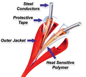
Construction – The sensor cable is comprised of two steel conductors individually insulated with a heat sensitive polymer. The insulated conductors are twisted together to impose a spring pressure between them, then wrapped with a protective tape and finished with an outer jacket suitable for the environment in which the Detector will be installed.
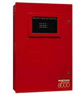
Protectowire FiberSystem 8000 PTS Series Controllers
The Protectowire FiberSystem 8000 has been designed for use as a linear heat detection system using state-of-the-art fiber optic sensing technology. The system consists of Type PFS Fiber Optic Sensor Cable and the PTS Controllers with related software. The PTS Series Controllers can be configured for various alarm criteria and can be connected to an approved fire alarm control panel using relay inputs and outputs. The system is specifically designed for high risk commercial and industrial hazards that demand high reliability and customized system features.
 Protectowire’s distributed temperature measurement is based on the proven Raman-Optical Time-Domain-Reflectometry (OTDR) technique. An optical laser pulse propagating through the sensor fiber gets scattered light back to the transmitting end, where it is analyzed using a patented code sequence measurement concept. The backscattered light is spread across a range of wavelengths. Some of these wavelengths are affected by temperature changes while others are immune. The intensity of the Raman signals is a measure of the temperature along the fiber. By very accurately measuring the difference in the signal intensity of the backscattered light an accurate temperature measurement can be made.
The local position of an alarm temperature is determined by measuring the arrival time of the returning light pulse similar to a radar echo showing the distance of a car or plane. This enables the FiberSystem PTS Controller to provide an exact location of a fire or hot spot anywhere along the sensor’s length. Temperatures are recorded as a continuous profile. The system is also capable of providing graphical representation of the fire size and direction of fire spread based upon the length of sensor in alarm.
Features
- Unique zoning capabilities. A single length of sensor can contain up to 256 zones.
- Multiple alarm initiating criteria by zone.
- Programmable custom operating logic.
- Capable of continuous temperature monitoring.
- Graphic display of temperature profile, fire size, and spread using computer interface.
- LAN Interface (TCP/IP) enables remote access from multiple locations.
System Design Features
Each PTS Controller is provided with four (4) programmable optically decoupled inputs, and twenty (20) programmable voltage free outputs (one trouble relay output and nineteen alarm relay outputs) for reporting to a main fire alarm panel. The trouble relay is normally closed and the alarm relays are normally open. Reverse logic can also be programmed. The resulting ability to switch between these two states provides several options for the user. For example, the output can be used to operate external audible signals or warning lamps.
The system can be integrated easily into your management platform (e.g. SCADA systems) by either directly communicating over Ethernet (TCP/IP) using SCPI (Standard Commands for Programmable Interface), or Modbus RS232, RS422, RS485 and TCP/IP. Also optionally available is a relay extension module that can trigger up to 256 relays per channel. The relay extension module is used to extend the twenty (20) standard embedded relay outputs provided in the PTS Controller.
System Architecture
- Controller: The PTS Controller is housed in a NEMA 1(IP20) type enclosure. The Controller contains the system operating software, transmitter, receiver, and digital processor.
- Transmitter: This unit contains the laser and its control. Its function is to generate the laser light by means of a semiconductor laser diode, and to control its overall operation.
- Receiver: This unit contains the entire optical design including coupler and optical receiver. Its function is to couple the laser light generated in the transmitter module to the sensor cable fiber. Additionally, the back-scattered light returned from the sensor fiber is distributed to the individual measurement channels, converted optically/electrically and amplified.
- Digital Processor: The digital processor controls the overall operation of the Controller and the temperature measurement process. Based upon the data it receives, the unit calculates the temperature profile along the sensor cable, controls alarm processing based upon stored zone definitions, manages the integrated four (4) inputs and multiple outputs, and communicates over the serial interface or via Ethernet.
The Controller is provided with active system status indicators, one (1) power disconnect switch, and one (1) reset switch mounted inside the enclosure. The LED visual indicators are grouped into six functional categories and signal the following information:
- TX/RX – Indicates communication activity between the PTS and controlling computer.
- FAULT – Indicates the PTS has an error or “trouble” condition.
- INIT – Blinks until internal temperatures settle, then stays on until booting is finished. Stays on if there is a boot error.
- RDY – Switches on after booting as readiness indicator.
- CHANNEL/ZONE – Indicates an active measurement on the corresponding channel.
- ALARM – On when the temperature value measured on the corresponding measuring channel exceeds the predefined alarm limits.
Fiber Optic Sensor Cable:
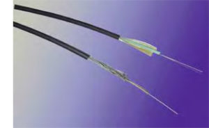 Protectowire PFS Series Fiber Optic Sensor Cable has unique advantages over other types of detectors, especially when difficult installation factors or severe environmental conditions are present. When used with a Protectowire FiberSystem 8000 PTS Controller, temperature measurement on the Sensor Cable takes place at periodic intervals to provide a continuous temperature profile.
The sensor cable consists of a non-metallic or stainless steel tube with an outside diameter of 1.2 – 1.8 mm (.05 – .07 inches). In the tube are two independent color-coded quartz fibers. Depending upon the model selected, the tube is clad with a layer of stainless steel wire or Aramid yarns. The sensor’s core is then sheathed in a flame retardant jacketing material to a diameter of 4 mm (.16 inches).
System Configuration:
- Power supply and a power source in compliance with UL requirements (10 to 30 VDC).
- The fiber optic sensor cable with PTS Controller shall be connected to a listed or approved fire alarm control panel through up to twenty (20) potential free contact outputs. Alarm and trouble conditions are conveyed by this means (19 alarm, 1 common trouble).
- Alarm confirmation of the fire alarm control panel occurs by means of up to four (4) opto-decoupled Controller inputs. Alternatively, this can also take place by means of a computer (if connected).
- The Controller can be connected to a PC by USB or LAN. This allows system parameterization to be carried out and measurement information to be read and displayed.
Functions
Operating Modes: Standard PTS Controllers are configured to operate as a Single Channel Single End device. In this configuration, if a fiber break caused by fire or mechanical damage should occur, the monitored area after the fiber break would be lost, and would no longer be capable of initiating an alarm.
When a Two Channel Controller is utilized, it incorporates additional optical connectors. These connectors allow the device to operate in a Dual Channel Single End mode, or a Dual Channel Closed Loop mode.
In a Dual Channel Single End configuration, the Controller performs single ended measurements on two separate fibers thus providing two distinct detection “channels.” In the Dual Channel Closed Loop operating mode, the sensor cable is installed in a loop, and the Controller performs measurements from both ends of the fiber. If a break should occur in the fiber, the entire sensor cable length continues to be monitored from both directions thus ensuring detection over the entire length of the sensor cable up to the point of the break.
Zones: A single length of sensor cable can be partitioned into different “zones” for various requirements (e.g. equipment shutdown, ventilation, and extinguishment release). Zones can be defined as desired and even overlapped, increasing system control capabilities. All FiberSystem 8000 PTS Controllers provide up to 256 alarm zones per channel. Individual alarm parameters and outputs can be assigned to each zone. The PTS Controllers also provide the ability to localize fire location with great accuracy. This ability is particularly useful for connecting the Controller to a control panel with extinguishing release capabilities.
Alarm Initiation: Temperature measurement on the sensor cable by the PTS Controller takes place at periodic intervals known as the measurement cycle time. An alarm is triggered at the end of the measurement cycle if any one of the following alarm criteria is exceeded in a zone:
- Maximum temperature per zone.
- Temperature difference between a measurement location and the zone average (zone differential).
- Temperature development per zone in terms of time (time differential / rate-of-rise).
Unlike conventional systems, these freely programmable alarm settings are user selectable and can be adapted individually by zone depending upon the specific requirements of the application. Different alarm sensitivities on the same sensor cable run allow precise and selective initiation of counter measures.
Fire Size: The PTS Controllers have the unique ability to provide information on the size of the fire by displaying relevant information in the visualization software. Fire size parameters can be individually set for five different sizes during parameterization. Default values are: Size 1 = < 5m (16 ft.); Size 2 = 5 to 10m (16 – 33 ft.); Size 3 = 10 to 50m (33 – 164 ft.); Size 4 = 50 to 100m (164 – 328 ft.); Size 5 = 100 to 500m (328 – 1640 ft.).
Direction of Fire Spread: Most fires have a dominant direction of spread caused by such factors as air current, construction, or combustibles. By knowing this propagation direction, the counter action of the emergency services can be directed to the less hazardous side of the fire. The visualization software provides three different options for determining the direction of fire spread.
- No direction – localized.
- Toward the PTS Controller (beginning of the sensor cable run).
- In the direction away from the PTS Controller (toward the end of the sensor cable run).
In the case of a sensor cable closed loop set-up, the “Point of Return” needs to be set to ensure that the propagation direction is displayed correctly.
Alarm Resetting: Resetting an alarm condition on the PTS Controller is done by using one of the four input contacts, the internally mounted reset button, or via the PTS Configuration software.
Communication
Configuration Software is provided with each FiberSystem 8000 Controller. This software can be easily adapted to specific customer requirements, and offers numerous options for displaying and processing the recorded alarm and temperature data. The software makes it possible to create multiple zones along a single length of sensor cable, select multiple alarm initiating criteria, provide unique alarm visualization graphics, and to configure zone related alarm generated outputs for event handling.
Interface Solutions
The FiberSystem 8000 can easily be integrated into SCADA Systems, direct process control or external connections to fire alarm control panels. The following special order accessory products can be used to extend the standard PTS interfaces:
Interface Box for Modbus: This device provides access via the Modbus protocol over RS232, RS422, or RS485, as well as over TCP/IP. The Modbus protocol offers, complete temperature trace data, each alarm parameter per zone, and several status conditions like fiber break.
Through a virtual host concept, the data is available for each sensor (channel) as a Modbus unit. This means that only one unit is required even for multiple channel operation. Ten thousand register holdings and three thousand register coil definitions can be flexibly assigned for each Modbus unit.
Relay Control: When the application requires the use of more than the twenty (20) embedded relay outputs of the PTS Controller, a Relay Controller Set should be used. In combination with the Relay Extension Set it is capable of controlling up to 256 relay outputs per channel. Each relay output can be flexibly assigned to any defined alarm condition.
The Relay Controller Set includes:
- Power Supply (More than 128 relays requires a second power supply)
- Pre-programmed Relay Controller
- One (1) digital output module, one (1) end module
- Eight (8) relays
The Relay Extension Set adds another Digital Output Module and eight (8) relays. As an example, to offer forty-eight relays, one Relay Controller Set and five Relay Extension Sets would be needed.